Module 04

Lead Implantation → Verification → Stimulation Field

Slides 16–20 | From mechanical precision to therapeutic precision

Original lecture slides 16–20 · Module 04 / 10

“THE FINAL LEAD POSITION IS ONLY THE BEGINNING OF THE THERAPEUTIC FIELD.”

From target to therapeutic field

  1. 01TARGET
  2. 02TRAJECTORY
  3. 03LEAD INSERTION
  4. 04FIXATION
  5. 05VERIFICATION
  6. 06LEAD RECONSTRUCTION
  7. 07STIMULATION FIELD
  8. 08PROGRAMMING
  9. 09THERAPEUTIC WINDOW

A DBS operation does not end when the lead reaches the target.

Learning objectives

By the end of this module you should be able to

  1. 01Describe the mechanical sequence of DBS lead implantation
  2. 02Explain why fixation is part of targeting accuracy
  3. 03Understand multimodal intraoperative verification
  4. 04Distinguish planned target from actual lead position
  5. 05Explain lead reconstruction
  6. 06Define VTA as a model-based estimate
  7. 07Explain why lead location and stimulation field are different concepts
  8. 08Describe the principle of directional DBS
  9. 09Recognize when directional steering may be useful
  10. 10Explain why directional DBS is not a substitute for accurate lead placement
  11. 11Define the therapeutic window
  12. 12Explain the four major programming levers
  13. 13Understand programming as electrical-field optimization

Original lecture slides

Slides 16–20

The slides below are reproduced exactly as delivered. Everything outside the slide panel is added study material.

Slide 16

Slide 16

Original lecture slide

100%
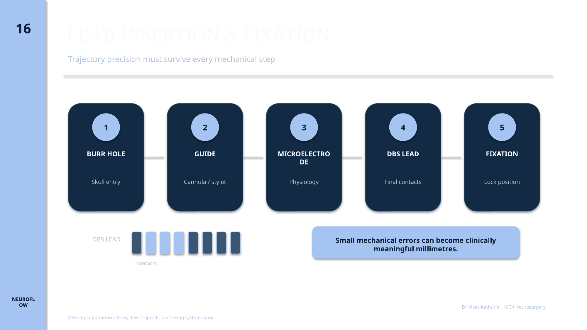
Original lecture slide 16 showing the DBS lead insertion and fixation sequence

LEAD INSERTION & FIXATION

  • Trajectory precision must survive every mechanical step
  • 1 BURR HOLE — Skull entry
  • 2 GUIDE — Cannula / stylet
  • 3 MICROELECTRODE — Physiology
  • 4 DBS LEAD — Final contacts
  • 5 FIXATION — Lock position
  • DBS LEAD
  • contacts
  • Small mechanical errors can become clinically meaningful millimetres.
  • DBS implantation workflow; device-specific anchoring systems vary.
  • Dr Vikas Kathuria | MCh Neurosurgery
Slide 17

Slide 17

Original lecture slide

100%
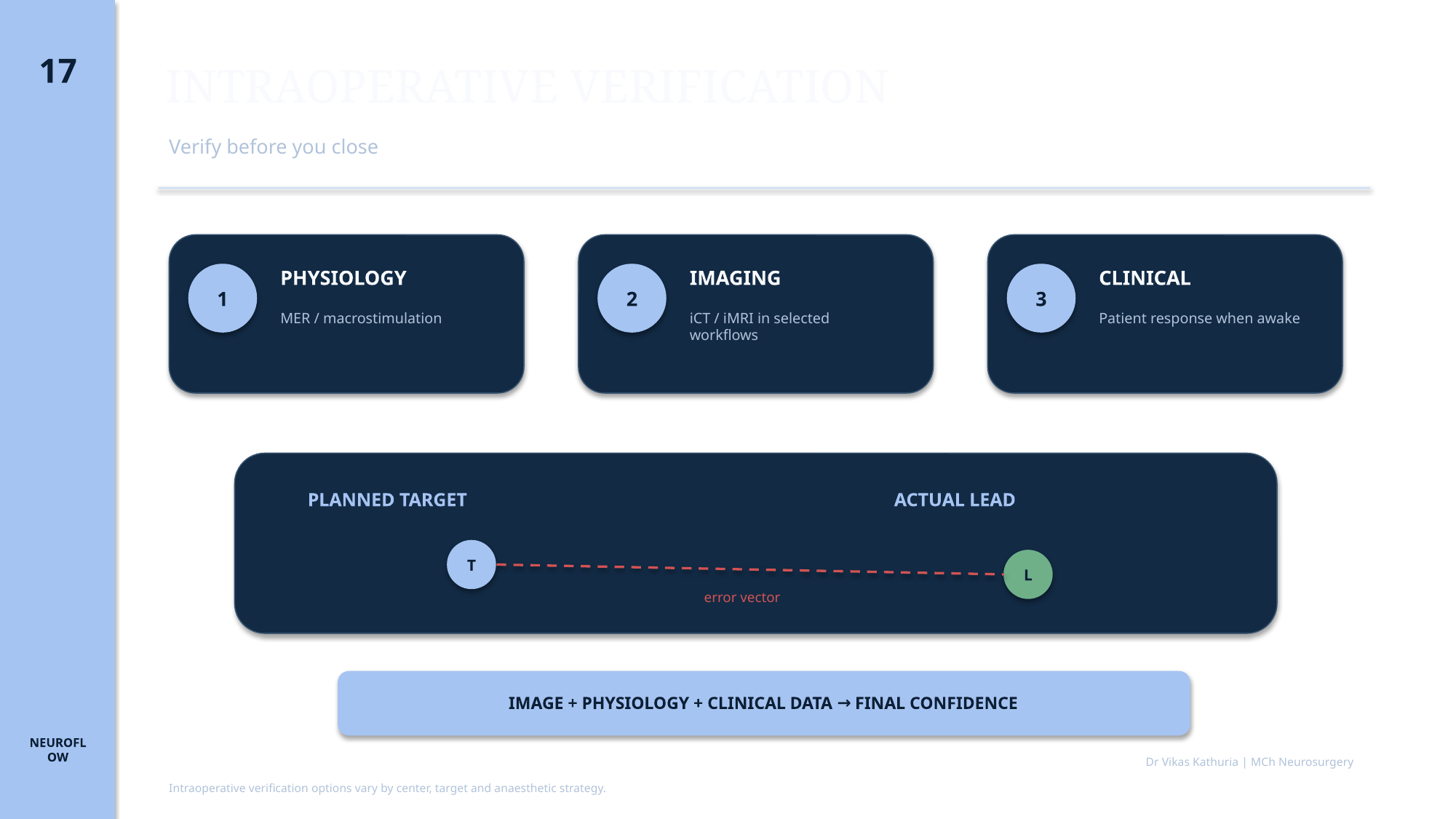
Original lecture slide 17 showing multimodal intraoperative verification

INTRAOPERATIVE VERIFICATION

  • Verify before you close
  • 1 PHYSIOLOGY — MER / macrostimulation
  • 2 IMAGING — iCT / iMRI in selected workflows
  • 3 CLINICAL — Patient response when awake
  • PLANNED TARGET
  • ACTUAL LEAD
  • error vector
  • IMAGE + PHYSIOLOGY + CLINICAL DATA → FINAL CONFIDENCE
  • Intraoperative verification options vary by center, target and anaesthetic strategy.
  • Dr Vikas Kathuria | MCh Neurosurgery
Slide 18

Slide 18

Original lecture slide

100%
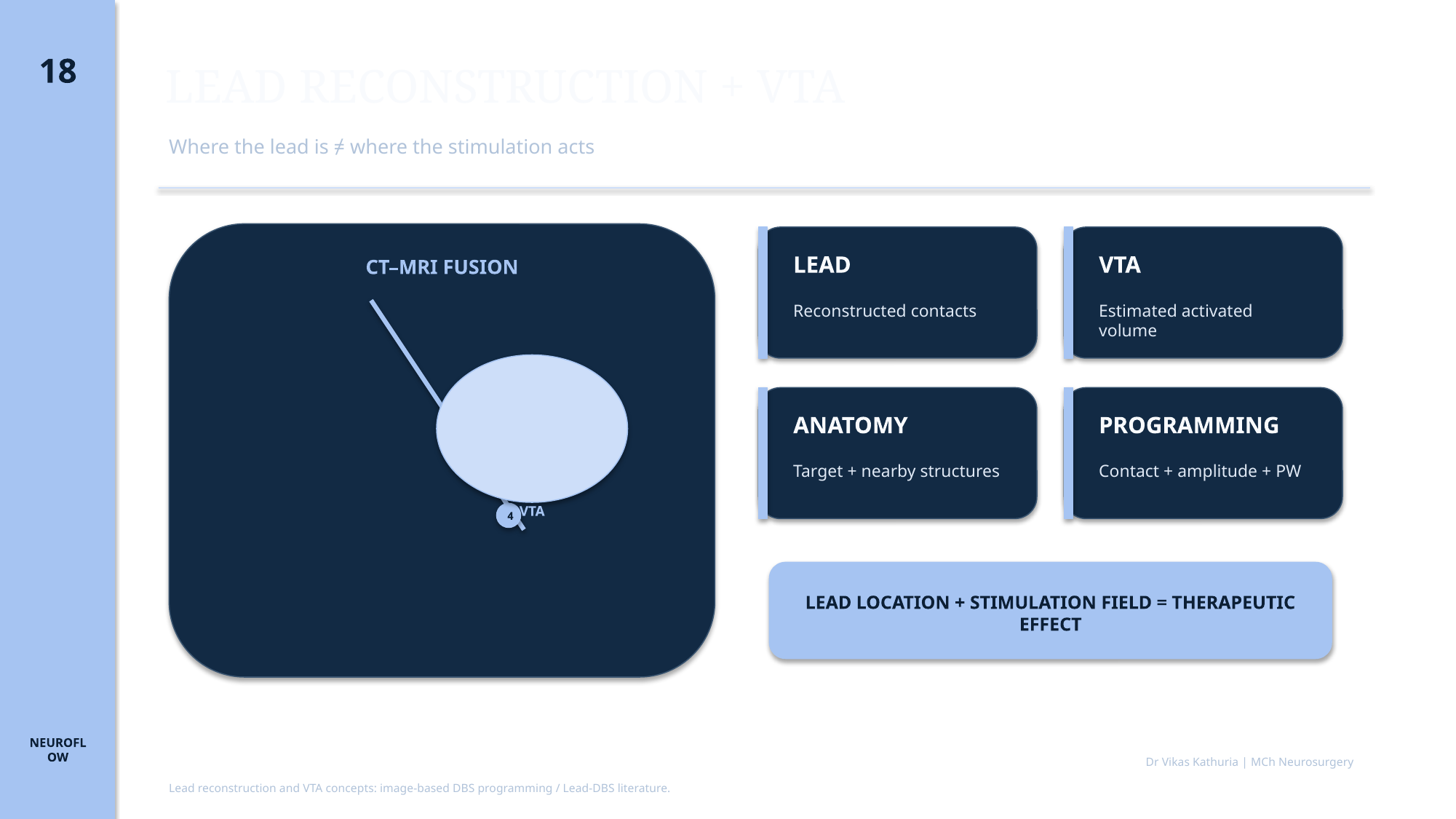
Original lecture slide 18 showing lead reconstruction and VTA concepts

LEAD RECONSTRUCTION + VTA

  • Where the lead is ≠ where the stimulation acts
  • CT–MRI FUSION
  • STN
  • 1
  • 2
  • 3
  • 4
  • VTA
  • LEAD — Reconstructed contacts
  • VTA — Estimated activated volume
  • ANATOMY — Target + nearby structures
  • PROGRAMMING — Contact + amplitude + PW
  • LEAD LOCATION + STIMULATION FIELD = THERAPEUTIC EFFECT
  • Lead reconstruction and VTA concepts: image-based DBS programming / Lead-DBS literature.
  • Dr Vikas Kathuria | MCh Neurosurgery

Slide 19

Slide 19

Original lecture slide

100%
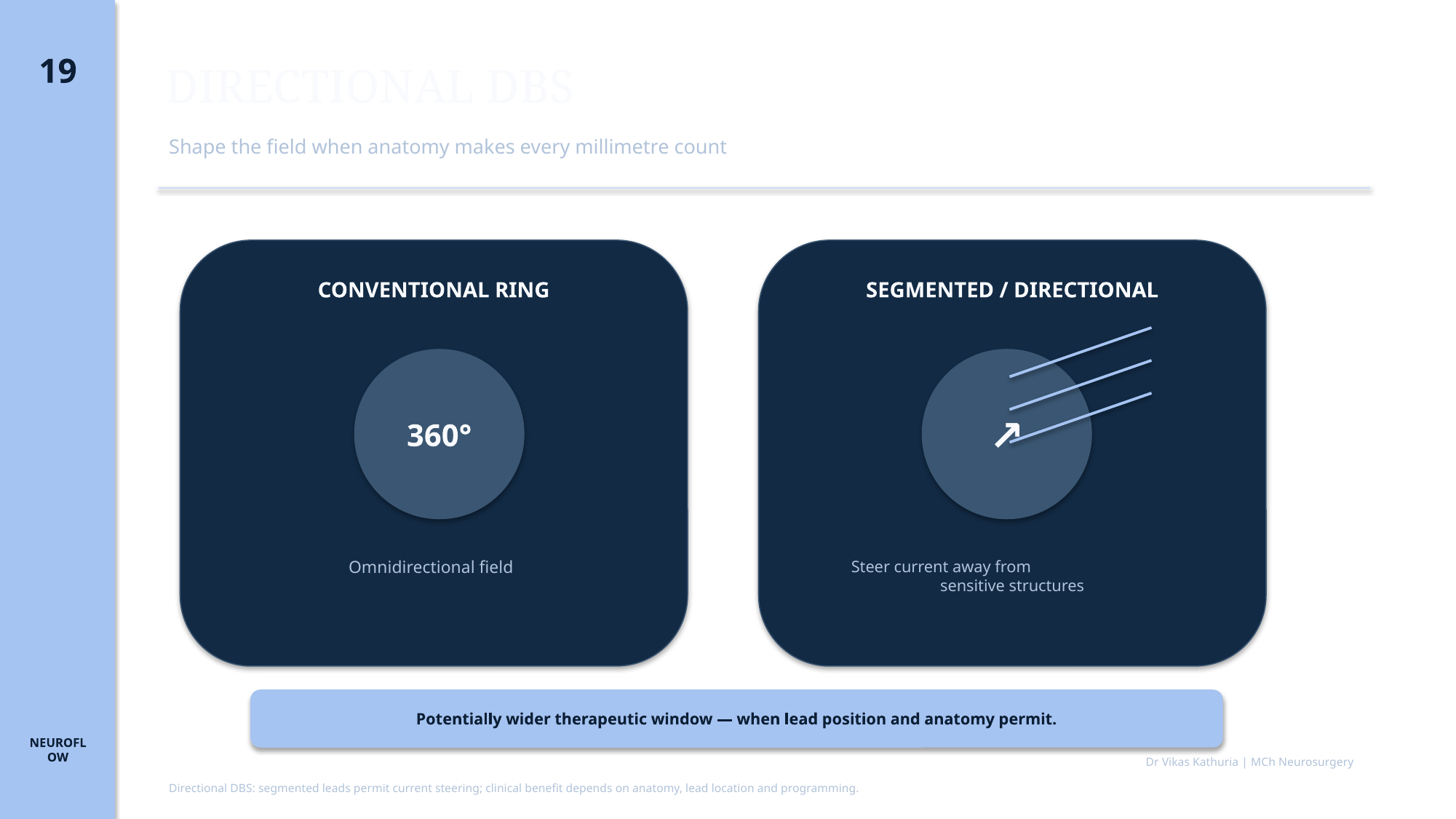
Original lecture slide 19 comparing conventional ring and segmented directional stimulation

DIRECTIONAL DBS

  • Shape the field when anatomy makes every millimetre count
  • CONVENTIONAL RING
  • 360°
  • Omnidirectional field
  • SEGMENTED / DIRECTIONAL
  • Steer current away from
  • sensitive structures
  • Potentially wider therapeutic window — when lead position and anatomy permit.
  • Directional DBS: segmented leads permit current steering; clinical benefit depends on anatomy, lead location and programming.
  • Dr Vikas Kathuria | MCh Neurosurgery

Slide 20

Slide 20

Original lecture slide

100%
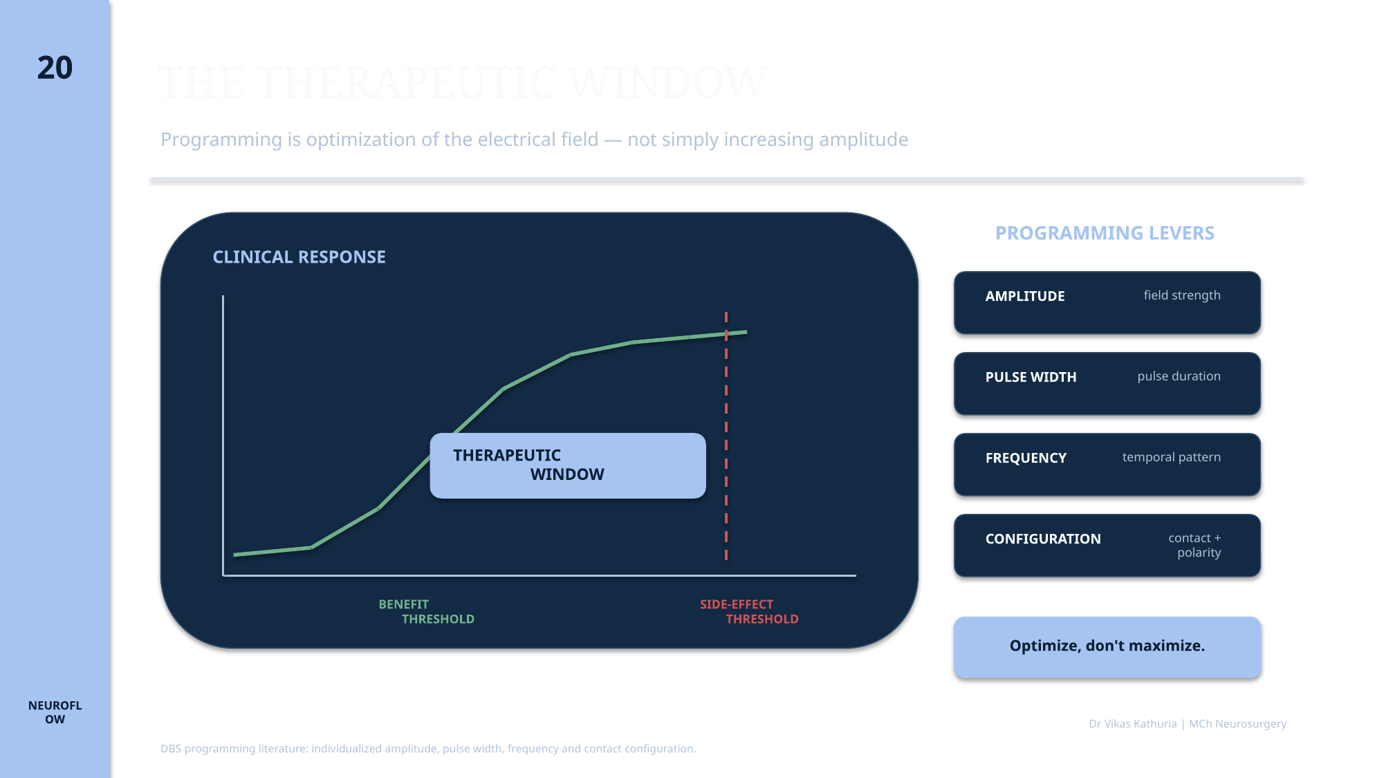
Original lecture slide 20 showing therapeutic window and programming levers

THE THERAPEUTIC WINDOW

  • Programming is optimization of the electrical field — not simply increasing amplitude
  • CLINICAL RESPONSE
  • THERAPEUTIC WINDOW
  • BENEFIT THRESHOLD
  • SIDE-EFFECT THRESHOLD
  • PROGRAMMING LEVERS
  • AMPLITUDE — field strength
  • PULSE WIDTH — pulse duration
  • FREQUENCY — temporal pattern
  • CONFIGURATION — contact + polarity
  • Optimize, don't maximize.
  • DBS programming literature: individualized amplitude, pulse width, frequency and contact configuration.
  • Dr Vikas Kathuria | MCh Neurosurgery

Expanded study material

From implantation to therapeutic field

Expand each topic without leaving Page 04. These modules are supplementary to the immutable original slides.

Interactive principle

Directional current steering

Explore spatial control conceptually—not a device-specific programming interface.

X

Centered field

Educational concept only. Directional stimulation may improve spatial control, but cannot guarantee avoidance or fully compensate for poor placement.

Interactive principle

Four programming levers

Programming changes the field through interacting variables; it is not amplitude escalation alone.

Field strength

Amplitude

Increasing amplitude generally changes field extent and intensity. Higher is not automatically better.

Programming variable→Stimulation field→Clinical effect

Case-based learning

Troubleshoot the entire chain

Reveal each discussion only after committing to a response.

Case 01

Mechanical deviation

An excellent preoperative plan and satisfactory physiology are followed by postoperative imaging showing deviation from the planned trajectory.

What should you do first?

Case 02

Lead is correct, effect is not

The lead is anatomically within the intended target. Benefit and dysarthria both occur at low amplitudes.

What does this suggest?

Case 03

Directional DBS near capsule

A directional lead lies close to the internal capsule. Ring-mode stimulation produces benefit but early capsular effects.

How could directional stimulation help?

Case 04

Interpreting VTA overlap

A modeled VTA overlaps the intended target and a nearby white-matter structure.

Does the VTA prove those fibers are activated?

Deep study material

Expanded study material

Established foundation

ESTABLISHED

Lead implantation, postoperative localization, individualized programming and the therapeutic-window concept form the core progression from surgery to therapy.

Model-supported reasoning

SUPPORTED

Image-based reconstruction, directional current steering and VTA visualization support patient-specific reasoning but do not replace clinical programming or judgment.

Developing precision

EMERGING

Patient-specific field models and pathway-informed optimization are increasingly sophisticated but remain model- and workflow-dependent.

Anatomy

Anatomy

Expanded study material for this section is written once the original slides for this module are supplied.

Surgical principles

Surgical principles

Burr hole, lead anchoring and strain relief

Extension tunnelling and IPG pocket

Avoiding brain shift and pneumocephalus

Physiology

Physiology

Expanded study material for this section is written once the original slides for this module are supplied.

Imaging

Imaging

Expanded study material for this section is written once the original slides for this module are supplied.

Programming

Programming

Expanded study material for this section is written once the original slides for this module are supplied.

Image placeholders

Images required for this module

Each placeholder states the image type, what is required, why it teaches and where a legitimate source should come from. No clinical image is fabricated.

Image placeholder

POSTOPERATIVE CT

Real clinical image required

Image typePostoperative lead reconstruction
DescriptionPostoperative CT fused to planning MRI showing DBS lead reconstruction relative to intended target.
Clinical purposeDemonstrates objective verification of achieved versus planned lead position.
Suggested sourceTo be supplied — publication, institution or own series
Copyright statusNot yet cleared
CaptionTo be written with the final image
AssociationModule 04

Image placeholder

DBS HARDWARE CHAIN

Real clinical image required

Image typeSchematic / diagram
DescriptionInteractive-style diagram of lead, anchor, extension connector and IPG with each component labelled.
Clinical purposeSupports hardware troubleshooting later in the curriculum.
Suggested sourceTo be supplied — publication, institution or own series
Copyright statusNot yet cleared
CaptionTo be written with the final image
AssociationModule 04

Image placeholder

OPERATIVE PHOTOGRAPH

Real clinical image required

Image typeBurr-hole photograph
DescriptionIntraoperative photograph of burr hole, lead insertion and anchoring device.
Clinical purposeShows the operative steps that determine lead stability.
Suggested sourceTo be supplied — publication, institution or own series
Copyright statusNot yet cleared
CaptionTo be written with the final image
AssociationModule 04

FROM TARGET TO THERAPY

01

TARGET

02

TRAJECTORY

03

LEAD INSERTION

04

FIXATION

05

VERIFICATION

06

LEAD RECONSTRUCTION

07

CONTACT CONFIGURATION

08

VTA / FIELD

09

THERAPEUTIC WINDOW

10

CLINICAL OUTCOME

  1. ANATOMY
  2. LEAD LOCATION
  3. ELECTRICAL FIELD
  4. PROGRAMMING
  5. CLINICAL EFFECT

THE LEAD IS PHYSICAL. THE THERAPEUTIC FIELD IS FUNCTIONAL. IF OUTCOME IS POOR, TROUBLESHOOT THE ENTIRE CHAIN.

Clinical pearls

  • Targeting accuracy must survive every mechanical step.
  • Verify before you close.
  • The actual lead position matters more than the intended coordinate.
  • Lead location is not the same thing as the stimulation field.
  • VTA is a model-based estimate, not a direct image of neuronal activation.
  • Directional DBS shapes current; it does not correct every targeting error.
  • The therapeutic window is multidimensional.
  • Optimize the electrical field—don't simply maximize amplitude.

Take-home message

THE SURGERY PUTS THE LEAD IN PLACE.THE THERAPEUTIC FIELD DETERMINES WHAT THE LEAD DOES.

  1. LEAD LOCATION
  2. STIMULATION FIELD
  3. THERAPEUTIC WINDOW
  4. PROGRAMMING
  5. CLINICAL EFFECT

References

Evidence supporting this module

  1. Hvingelby V, Khalil F, Massey F, et al. Directional deep brain stimulation electrodes in Parkinson's disease: meta-analysis and systematic review of the literature. J Neurol Neurosurg Psychiatry. 2025;96(2):188-198.
  2. Horn A, Kühn AA. Lead-DBS: a toolbox for deep brain stimulation electrode localizations and visualizations. Neuroimage. 2015;107:127-135.
  3. Horn A, Li N, Dembek TA, et al. Lead-DBS v2: towards a comprehensive pipeline for deep brain stimulation imaging. Neuroimage. 2019;184:293-316.
  4. Butson CR, Cooper SE, Henderson JM, McIntyre CC. Patient-specific analysis of the volume of tissue activated during deep brain stimulation. Neuroimage. 2007;34(2):661-670.
  5. Butson CR, McIntyre CC. Current steering to control the volume of tissue activated during deep brain stimulation. Brain Stimul. 2008;1(1):7-15.
  6. Steigerwald F, Matthies C, Volkmann J. Directional deep brain stimulation. Neurotherapeutics. 2019;16(1):100-104.
  7. Yearley AG, Chua M, Horn A, et al. Deep brain stimulation lead localization variability comparing intraoperative MRI versus postoperative computed tomography. Oper Neurosurg (Hagerstown). 2023;25(5):415-422.
  8. Mirzadeh Z, Chapple K, Lambert M, et al. Validation of CT-MRI fusion for intraoperative assessment of stereotactic accuracy in DBS surgery. Mov Disord. 2014;29(14):1788-1795.

“The surgery puts the lead in place. The therapeutic field determines what the lead does.”

Next module · 05Advanced Programming — STN, GPi & VIM / DRT